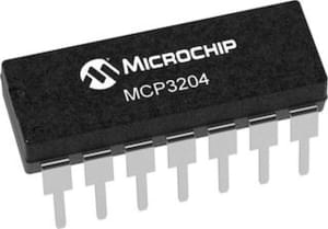
MCP3204 & MCP3208 12-Bit A/D Converters
The Microchip Technology Inc. MCP3204 & MCP3208 devices are successive approximation 12-bit Analog-to-Digital (A/D) converters with on-board sample and hold circuitry. This component is common for both device types. Configure both devices as MCP3204 and observe the maximum number of channels as per variant used.

Component/Hub
The MCP3204 component allows you to use MCP3204 or MCP3208 12-Bit A/D Converter (datasheet) in ESPHome. The MCP3204 is a 4-channel and MCP3208 is an 8-channel device. It uses the SPI Bus for communication.
Once configured, you can use any of the 4 or 8 pins (depending on device variant) as sensors for your projects.
Each pin will respond with a voltage calculated off of the reference_voltage (default is 3.3V).
It calculates the voltage by multiplying the reference_voltage * value on the pin (basically the percentage of VREF)
Most configurations will set the reference_voltage = VREF pin
# Example configuration entry
mcp3204:
  cs_pin: GPIOXX
  reference_voltage: 3.3V
Configuration variables
- id (Required, ID): The id to use for this MCP3204 component.
- cs_pin (Required, Pin Schema): The SPI cable select pin to use.
- reference_voltage (Optional, float): The reference voltage. Defaults to
3.3V.
Sensor
The mcp3204 sensor allows you to use your MCP3204 or MCP3208 12-Bit A/D Converter sensors with ESPHome.
First, setup a MCP3204 Hub for your MCP3204/8 sensor and then use this
sensor platform to create individual sensors that will report the voltage to Home Assistant.
# Example config of sensors.
# This is a small 1.5v solar panel power rail attached to pin 0
# of the MCP3204
sensor:
  - platform: mcp3204             # Attached to pin 0 of the MCP3204.
    id: solar_voltage
    number: 0                     # MCP3204 pin number

# In case MCP3208 is used. you can specify pin number > 4
  - platform: mcp3204             # Attached to pin 7 of the MCP3208.
    id: supply_voltage
    number: 7                     # MCP3208 pin number

# Measures difference between CH0 (IN+) and CH1 (IN-)
  - platform: mcp3204             # Attached to pins 0-1 of the MCP3208 (differential pair).
    id: thermocouple_voltage
    number: 0                     # MCP32xx pin number
    diff_mode: true               # Enable differential mode
Configuration variables
- mcp3204_id (Required, ID): The id of the parent MCP3204 component.
- number (Required, int): The pin to measure on the MCP3204/MCP3208
- update_interval (Optional, Time): The interval to check the sensor. Defaults to
60s. - diff_mode (Optional, boolean): Enable differential mode measurement. Defaults to
false. - All other options from Sensor.
Operating Modes
The MCP3204/3208 supports two input configurations:
Single-Ended Mode (default)
Each channel measures voltage independently relative to ground. The MCP3204 provides 4 channels, and MCP3208 provides 8 channels. This is the default operating mode when diff_mode is not specified or set to false.
Differential Mode
When diff_mode: true, channel pairs measure the voltage difference between two inputs (IN+ and IN-). Specify the positive input channel number with the number parameter. The next sequential channel automatically becomes the negative input (IN-).
Available differential pairs:
- MCP3204: 2 pairs (CH0/CH1, CH2/CH3)
- MCP3208: 4 pairs (CH0/CH1, CH2/CH3, CH4/CH5, CH6/CH7)


